A shaft lock is useful when you need to secure a hub, pulley, sprocket, coupling, or rotor to a cylindrical shaft without cutting a keyway, but its success depends on friction, fit, preload, and hub strength. By the end, you will be able to match the locking method to the shaft form, calculate the loads that matter, and identify when a keyed or splined connection is the safer choice.
Key takeaways
- Use shaft locks on smooth cylindrical shafts when keyless torque transfer is suitable.
- Compare clamping locks with keys, collars, and splines before choosing a retainer.
- Size for torque, thrust, shock loads, speed, shaft diameter, and hub fit.
- Inspect contact surfaces, tightening sequence, fasteners, and signs of fretting or slip.
What a shaft lock holds, and which shaft forms suit it
A useful shaft lock definition is a clamping assembly that secures a hub, pulley, sprocket, coupling, or rotor to a shaft through radial pressure and friction. It restrains rotational movement and, when rated for thrust, axial movement without a machined keyway.
That makes it the right connection for a plain cylindrical shaft when you need adjustable hub positioning and straightforward removal.
The connection fails by slipping when combined torque and axial force exceed its friction capacity. Do not confuse tightening torque with transmitted torque: the first creates clamping force; the second is the load the joint must carry. Surface condition, hub stiffness, installation accuracy, shock, reversing duty, and temperature all affect the result.
At high speed, check balance, runout, centrifugal effects, and added rotating mass before approving the lock.
| Shaft form | Suitability | Decision point |
|---|---|---|
| Plain cylindrical shaft | Best match | Use when the shaft is smooth, round, and free from oil, burrs, and damage. |
| Keyed shaft | Conditional | Use only when the lock bore and supplier instructions allow the keyway; otherwise choose a keyed connection. |
| Splined shaft | Usually unnecessary | Splines already provide positive torque transfer; select a compatible splined hub instead. |
| Threaded shaft | Poor fit | Threads interrupt friction contact; use a threaded retainer or purpose-designed locking system. |
| Shaft with a shoulder | Suitable | Let the shoulder locate the hub axially, but verify the shaft lock carries the remaining thrust. |
How a shaft lock compares with keys, collars, and other retainers
If friction-locking is not enough, choose a key, spline, or polygonal profile that carries torque through positive mechanical locking. A shaft lock relies on clamping pressure and friction; overload can make the hub slip without breaking a visible part, damaging both contact surfaces. It is also not a torque limiter or brake.
| Option | What it means | When it applies |
|---|---|---|
| Shaft lock | Clamps a plain round shaft through radial pressure | You need adjustable axial positioning, low machining effort, and moderate shock or reversal |
| Key and keyed hub | A key transmits torque through bearing and shear | Use when torque must remain available after friction loss, or a standard requires a positive drive |
| Splined shaft | Multiple teeth share torque around the shaft circumference | Choose for high-cycle reversal, high torque density, or frequent sliding engagement |
| Polygonal profile | Non-round shaft transmits torque across its faces | Use when you need positive drive with low backlash and no separate key |
| Shrink disc or clamping hub | A larger friction joint spreads clamp pressure over the hub | Choose when friction is acceptable but a higher-capacity, compact joint is required |
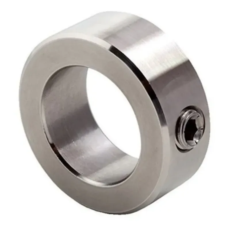
| Shaft collar or set-screw collar | Usually restrains axial movement rather than torque | Use for stops, sensors, or light axial retention, not a primary drive connection |
Select a keyed shaft when shock loads, repeated reversals, or a governing design standard rule out slip. Select a splined shaft when cycle life and torque density matter more than simple machining. A shaft lock remains the better choice for a clean, accessible plain shaft when its torque, thrust, speed, and hub-stiffness limits are verified.
How to size a lock for torque, thrust, shock, and speed
Do not accept a shaft lock’s torque rating until you check the actual transmitted torque and axial thrust together. A belt pull, propeller thrust, screw thrust, or gear force consumes friction capacity; a lock rated for torque alone can slip when both loads act at once.
1. Calculate the transmitted torque at the shaft, then apply the manufacturer’s specified service factor for acceleration, shock, braking, and reversal. Do not compare this value with the screw tightening torque: tightening torque is wrench input that creates clamping force.
2. Calculate the maximum axial load and compare it with the lock’s axial holding capacity. Include startup thrust, belt tension changes, helical-gear force, screw load, and any external pull. Use the manufacturer’s torque-thrust interaction curve or combined-load equation rather than checking each rating independently.
3. Confirm that the resulting demand stays below the lock’s friction torque capacity at the specified shaft diameter, hub bore, contact length, materials, surface condition, and tightening torque. Published ratings are conditional, not universal capacities.
4. Check the maximum speed, balance, temperature, and cyclic duty stated for that exact lock. Clean, dry clamping faces are essential; oil or grease can lower friction and reduce capacity. Lubricate only the locations the manufacturer specifies, usually screw threads rather than contact faces.
If the calculation depends on frequent severe shocks, repeated reversal, or positive torque after friction loss, choose a keyed or splined drive instead. A shaft lock is not a brake or overload device; exceeding capacity can make the hub slip and damage both surfaces without breaking the lock.
How shaft and hub fit determine whether the connection will hold
The connection will hold only if the lock develops its specified contact pressure without distorting the shaft or splitting the hub. Before ordering, match the manufacturer’s bore, shaft diameter tolerance, contact length, and hub-wall requirements to an actual drawing, not a nominal shaft size.
Published torque also assumes the specified tightening torque and suitable contact surfaces.
1. Measure the shaft at several axial and angular points. Check diameter, roundness, taper, and runout against the locking assembly’s stated limits; an oversized shaft can prevent assembly, while an undersized or lobed shaft reduces contact pressure.
2. Confirm the required surface finish and inspect for rust, burrs, dents, plating buildup, oil, and paint. A rough or contaminated surface changes friction and creates leakage paths between the shaft and hub.
3. Verify the hub bore tolerance, contact length, outside diameter, and minimum wall thickness. Thin cast-iron, aluminium, or welded hubs can crack as the assembly expands radially.
4. Record keyway dimensions before choosing a lock for an existing shaft. A keyway interrupts the friction contact, so confirm whether the manufacturer permits it and whether its width, depth, and length fall inside the approved arrangement.
5. Check shaft and hub materials, hardness, coatings, operating temperature, and stress concentration near shoulders or grooves. These details affect friction, deformation, and the safe tightening torque.
When sourcing related automation components from OLE Automation Inc, provide the shaft-lock supplier with the shaft drawing and hub material rather than ordering by diameter alone. That allows the catalogue rating to be checked against the actual fit.
How to install, inspect, and decide when to use a keyed or splined drive
Install the lock on clean, burr-free shaft and hub surfaces, then follow the manufacturer’s tightening sequence and number of passes. Use a calibrated torque tool; tightening torque is the wrench input that creates clamp force, not the transmitted torque the connection can carry.
- Slide the hub to its required axial position without forcing the lock over burrs or a shoulder.
- Tighten the screws in the specified alternating or star pattern, usually in multiple passes. Tightening one screw fully first can distort contact pressure and reduce capacity.
- Retorque after the first pass if the installation instructions require it, then mark each screw for inspection.
- Measure hub or coupling runout with a dial indicator before commissioning. Excessive runout adds eccentricity, imbalance, and centrifugal loading at speed.
- Record screw torque, shaft diameter, hub material, and the lock’s rated torque and axial load. Do not treat a published rating as universal; it depends on fit, contact length, wall thickness, friction, and materials.
Reject a shaft lock when the application demands positive torque transmission beyond friction capacity, repeated shock, or severe reversing duty. A slipping hub can score both surfaces without breaking the lock.
Choose a keyed or splined drive when torque reverses frequently, overloads are credible, or a fail-safe mechanical drive is required; splines also suit repeated axial sliding when the profile and lubrication support it. Reject the lock for a high-speed rotor if its added mass, balance, or runout cannot meet the rotor’s limits.
Frequently asked questions
What does a shaft lock hold, and which shaft forms suit it?
A shaft lock secures a hub, pulley, sprocket, coupling, or rotor through radial clamping pressure and friction. It suits clean, round cylindrical shafts with enough surface area for the specified contact pressure.
How does a shaft lock compare with a key, collar, or other retainer?
A shaft lock avoids machining a keyway and can reduce backlash, while a key provides positive torque transmission. A collar primarily locates or restrains axial movement and does not replace a torque-rated shaft connection.
How do you size a shaft lock for torque, thrust, shock, and speed?
Check the manufacturer’s torque and axial-load ratings against transmitted torque, thrust, shock or reversing loads, shaft diameter, and operating speed. Apply the stated service factor instead of sizing from nominal motor power alone.
How do shaft and hub fit determine whether the connection will hold?
The shaft and hub must meet the lock manufacturer’s diameter, roundness, surface-finish, straightness, and fit limits. Remove oil, burrs, paint, and corrosion from the clamping surfaces before assembly.
When should you use a keyed or splined drive instead?
Choose a keyed or splined connection when the load exceeds the shaft lock’s rating, shock and reversing torque demand positive mechanical engagement, or the shaft and hub cannot meet the required fit and surface conditions.