A cross roller bearing is chosen when a mechanism must hold position against more than one kind of force, especially an offset load that creates pitch or yaw torque. By the end, you will be able to match the bearing form to linear, rotary, or oscillating motion, identify suitable machinery applications, and build a selection request around loads, accuracy, preload, and installation conditions.
Key takeaways
- Use crossed rollers when one bearing must resist radial, axial, and moment loads.
- Select the bearing form after defining rotation, linear travel, or oscillating motion.
- Trade maximum rigidity against speed, friction, lubrication, and contamination exposure.
- Specify load direction, moment, stroke, accuracy, preload, environment, and mounting space.
How a Cross Roller Bearing Carries More Than One Load
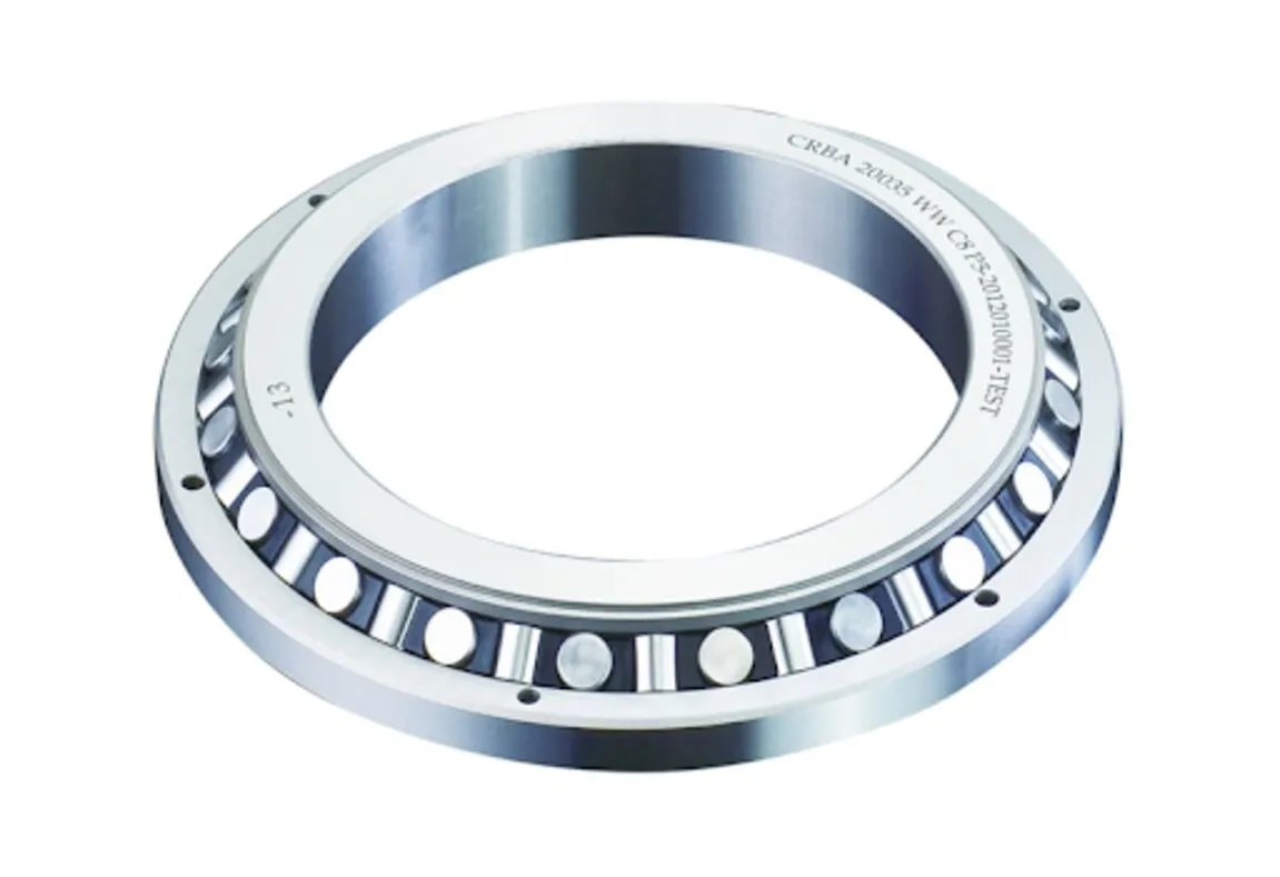
The cross roller bearing definition is straightforward: it is a bearing in which cylindrical rollers sit between inner and outer raceways, with adjacent rollers oriented at 90 degrees to one another. These crossed cylindrical rollers contact the raceways along lines rather than points, creating a stiff support in a compact radial section.
One bearing can resist three forms of loading:
- radial load: force acting perpendicular to the shaft or guide axis
- axial load: force acting along that axis
- moment load: overturning force created when a load acts away from the bearing’s center
That moment capacity matters when an offset payload, tooling reaction, or cable drag tries to pitch, yaw, or roll an axis. A bearing sized only for radial and axial capacity can still fail the application’s rigidity requirement.
Manufacturers apply controlled preload to remove internal clearance, which limits wobble and improves repeatable positioning. The rollers also distribute contact over long lines, helping the bearing resist deflection under load. These features suit rotary tables, precision stages, and inspection mechanisms that need compact support with high stiffness.
Do not treat the bearing itself as a guarantee of accuracy. Runout and rotation error also depend on preload, shaft and housing geometry, mounting-flatness, and assembly adjustment. Dirt, moisture, or unsuitable grease can increase torque and damage the raceways before fatigue life is reached.
The Machinery That Uses Cross Roller Bearings
An offset payload can make a precision stage pitch, yaw, or roll instead of moving cleanly. Cross roller bearings resist that overturning moment in a compact space, reducing deflection, runout, and the need for separate guide or moment-support elements.
- Semiconductor inspection stages use crossed-roller ways for short, precise travel. They control friction variation and lost motion while a sensor scans wafer features.
- Electronics inspection equipment uses them to keep probes, cameras, and test heads aligned under changing moment loads. The result is repeatable positioning instead of tip-induced measurement error.
- Optical equipment uses rotary rings or linear ways where lens, mirror, or sensor alignment must remain stable. High rotational rigidity limits angular drift and runout.
- Camera and lens positioning mechanisms use them for smooth focus, zoom, or aiming adjustments. Their low profile preserves a compact optical package while resisting tilt from an offset lens.
- Machine-tool rotary tables and indexing tables use rotary rings to hold angular accuracy under cutting or indexing loads. The bearing resists axial, radial, and overturning forces without adding a separate thrust assembly.
- Robot wrist and arm joints use rotary rings to support compact joints carrying eccentric tools. Rigidity limits tool-point deflection during acceleration and reversal.
- Measuring instruments and medical imaging mechanisms use them when repeatable rotation matters more than high speed. Their stiffness helps maintain probe or detector alignment.
- Wafer-handling equipment uses crossed-roller linear guides for controlled short strokes. Do not use that guide for continuous rotation; specify a crossed-roller rotary ring instead.
Accuracy still depends on preload, mounting flatness, housing geometry, and assembly adjustment. A high-grade bearing installed in a distorted housing can lose its advertised runout and stiffness.
Choose the Bearing Form After Identifying the Motion
Start with the motion: identify whether the mechanism needs linear motion, rotary motion, or limited-angle oscillation. Choose a rotary cross roller bearing for a rotating axis that needs radial, axial, and overturning-moment support in one compact unit. Choose a guide for constrained travel; do not ask a linear guide to rotate continuously.
| Form | Motion and load behaviour | Choose it when |
|---|---|---|
| Rotary cross roller bearing | Rotary motion with radial, axial, and moment capacity | Precision rotary positioning, indexing, or an offset payload |
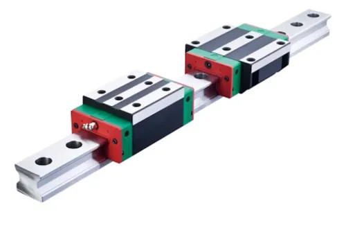
| Crossed-roller linear guide | Linear motion on crossed cylindrical rollers; high rigidity over a short stroke | Stages, optical mechanisms, measuring instruments, or wafer handling |
| Recirculating-ball linear guide | Linear motion through recirculating balls and a rail; suited to longer travel | Machine axes where travel and speed matter more than maximum moment rigidity |
| Angular-contact bearing | Rotary motion with combined radial and axial capacity; usually a higher-speed choice | Spindles or axes where speed and lower friction outweigh extreme moment stiffness |
| Deep-groove bearing | Rotary motion, mainly radial load with modest axial load | General shafts without substantial overturning moment |
A crossed-roller linear guide and a recirculating-ball linear guide both constrain translation, but the crossed rollers provide separated contact lines and strong resistance to pitch, yaw, and roll. A rotary ring uses the same principle around a circumference; its preload and many line contacts increase friction and heat.
For continuous high-speed rotation, compare an angular-contact bearing or deep-groove bearing before selecting a crossed-roller ring. For limited-angle oscillation, check reversal frequency, lubrication, and false-brinelling risk rather than treating the application as ordinary continuous rotation.
Balance Rigidity Against Speed, Friction, and Contamination
A crossed-roller bearing buys high rigidity and moment resistance at the cost of speed, friction, and cleanliness margin. Its separated contact lines resist pitch torque and yaw torque without widely spaced rails or a second support bearing, but every added contact force raises drive effort and heat.
- Machine-tool tables gain accurate indexing and resistance to cutting forces, especially with an offset workpiece. High preload limits runout and table deflection, but increases starting torque, running torque, and sensitivity to housing distortion; a thin-section ball bearing can suit a faster axis better.
- Robot wrists and arm joints gain a compact section and strong overturning-load support. The trade-off is limited high-speed capability and greater friction than a lightly loaded ball bearing, which can reduce servo responsiveness and increase motor heat.
- Medical mechanisms gain smooth, repeatable rotary positioning in a small envelope. Specify low running torque and controlled lubrication carefully: excess preload can create heat and positioning error, while inadequate protection lets cleaning fluids or wear particles damage the raceways.
- Wafer-handling equipment gains precise short-stroke guidance or compact rotary support. Crossed-roller ways suit clean, limited-travel stages; protect them from particles because contamination can cause stiction, noise, and local raceway damage.
Preload is not the same as “zero clearance.” Request the maker’s preload designation, torque data, speed limit, lubrication method, seal or cover arrangement, and allowable contamination conditions. Choose a different arrangement when continuous high speed, low friction, or an unsealed environment matters more than maximum rigidity.
Turn the Application Into a Bearing Specification
Size the bearing from the worst combined load case, not from shaft diameter alone. Record radial, axial and moment loads, bearing span, stroke, travel speed, acceleration, duty cycle, temperature and mounting space.
Convert the combined forces and moments into an equivalent load, then request fatigue-life calculation to ISO 281 and a static safety check to ISO 76. Catalog capacity assumes the specified mounting dimensions and rigid supports; a distorted housing can overload only part of the roller set.
- State the required accuracy as runout, parallelism, rotation accuracy and stiffness, rather than saying “high precision.”
- Request the manufacturer’s preload designation. Higher preload increases rigidity but also starting torque, heat and sensitivity to mounting error; “zero clearance” is not a sufficient specification.
- Provide shaft, housing, shoulder and mounting-flatness tolerances. Install against measured, clean reference faces, tighten in the maker’s sequence and verify torque, friction and runout after assembly. OLE Automation Inc can help compare a linear-guide alternative when the stated motion is linear rather than rotary.
| Option | What it means | When it applies |
|---|---|---|
| Crossed-roller rotary ring | Preloaded rotary support with higher friction and heat | Precision indexing or limited-angle rotation |
| Crossed-roller way | Constrained linear motion | Short-stroke stages; never continuous rotation |
| Angular-contact ball bearing | Lower friction and higher speed potential | High-speed rotation where moment rigidity is less demanding |
Frequently asked questions
How does a cross roller bearing carry more than one load?
Its adjacent cylindrical rollers sit at 90-degree orientations, allowing the bearing to support radial, axial, and overturning moment loads through line contact.
What machinery uses cross roller bearings?
They are used in high-precision machinery such as CNC equipment, industrial robots, inspection systems, semiconductor equipment, and rotary or linear positioning stages.
How do you choose the right cross roller bearing form?
Identify whether the application uses rotary, linear, or oscillating motion, then match the bearing form to its travel, mounting arrangement, load directions, and accuracy requirements.
What should you balance before specifying a cross roller bearing?
Compare required rigidity with operating speed, friction, preload, lubrication needs, contamination risk, service life, and available installation space.