Smooth linear travel depends on more than the bearing bush itself: the shaft, housing, load arrangement and installation tolerances all determine whether the carriage moves freely or binds. By the end, you will be able to match an INS bush to its shaft, calculate the important loads, and decide when another guide system is the better choice.
Key takeaways
- Match the bearing bore and shaft diameter to the specified fit and clearance.
- Align supported shafts carefully to prevent binding and uneven ball loading.
- Choose open bearings for supported shafts and closed bearings for unsupported shafts.
- Use the specified lubricant and verify seals, material, dimensions and traceability before installation.
How the sleeve and recirculating balls carry a moving shaft
An INS linear bearing bush turns sliding contact into rolling contact. Its linear bearing sleeve houses an internal ball cage that guides balls around the shaft. As the sleeve moves, recirculating balls travel through loaded raceways against the shaft, then return through unloaded passages to repeat the circuit.
The working parts are:
- Hardened shaft: provides the cylindrical raceway and carries radial load.
- Linear bearing sleeve: holds the ball tracks and connects to the moving carriage.
- Internal ball cage: spaces and redirects the recirculating balls.
The loaded balls share contact around the shaft, supporting the carriage while reducing resistance and stick-slip. The bush can travel repeatedly along a shaft, but practical stroke ends at the shaft length, a stop, or the point where the bush could run off.
A longer axis needs shaft retention or a supported arrangement; it does not require a longer bush.
Use a hardened precision shaft, not ordinary mild-steel rod. A soft, bent, or scored shaft disrupts ball contact, increases noise and friction, and damages the raceways. Seals retain grease and block dust, although contact seals add drag. That trade-off is worthwhile where abrasive contamination would rapidly shorten bearing life.
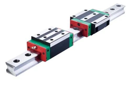
Unlike a HIWIN profile rail and carriage, this system runs on a cylindrical shaft rather than a matched profiled rail. The bearing’s movement quality therefore depends on the shaft and housing as much as on the bush.
Which shaft and fit dimensions determine bearing performance
Before you specify, match the bush to shaft diameter, usable stroke, radial load, and the way the carriage is mounted. The shaft is a load-bearing raceway, not just a rod: hardness, surface finish, shaft straightness and roundness affect friction, noise, load sharing, and service life.
| Check | Confirm | Failure if ignored |
|---|---|---|
| Shaft diameter | Nominal diameter and shaft tolerance match the INS bush bore and clearance | Excess clearance causes play; an undersized fit raises friction |
| Usable stroke | Shaft travel exceeds commanded stroke, including overtravel and end clearances | Balls reach an unsupported or contaminated zone |
| Shaft geometry | Hardened shaft with specified finish, straightness and roundness | Scoring or runout overloads balls and creates vibration |
| Load and motion | Radial load includes carriage weight, acceleration, deceleration, process force, speed and moment load | Static weight alone understates raceway stress |
| Housing fit | Bore tolerance, roundness, alignment and press-fit method suit the bush | A tight or distorted bore reduces internal clearance |
| Installation space | Mounting clearance allows alignment, seals, lubrication and shaft support | Restricted access can force misalignment or prevent maintenance |
| Environment | Contamination, moisture, chips and temperature suit the selected seals and lubricant | Abrasive debris rapidly damages balls and raceways |
Check moment load separately when cutting, pressing or gripping forces act away from the bearing plane. Two bushes or parallel shafts do not share load equally unless shaft parallelism, housing alignment and carriage stiffness are controlled.
Compare required accuracy with thermal growth, shaft deflection and backlash elsewhere in the axis. A tighter bush cannot correct a bent shaft or inaccurate housing. Specify the mating shaft and housing together, rather than choosing the bush from diameter alone.
How load sharing, alignment and preload affect accuracy
Two bushes on one shaft do not automatically share the radial load equally. Housing tolerances, carriage stiffness, and shaft parallelism decide which bush carries the force; with parallel shafts, a small spacing or angular error can overload one ball circuit while the other carries little.
The result is higher friction, uneven motion, noise, and shorter life.
A moment load is especially damaging because force applied away from the bearing span creates a tilting force, not just a radial force. That tilt concentrates contact at one end of a bush and can cause:
- Binding as the carriage moves
- Local raceway wear or brinelling during stops and shocks
- Positioning error from elastic deflection and uneven clearance
Preload or reduced clearance removes radial play and improves repeatability, but it also raises running resistance, heat, and sensitivity to shaft straightness, housing alignment, and thermal growth. Use clearance where long travel, contamination, temperature change, or imperfect parallelism matters more than minimum play.
Do not judge life from dynamic load alone. The usual ball-bearing estimate is L10 = (C/P)^3, where L10 is the distance or cycle count that 90% of a sufficiently large group is expected to reach under stated conditions.
A high moment load or shock can exceed the static rating and permanently deform the raceway before calculated L10 is reached.
When to use open, closed, supported or alternative guide systems
Choose a closed linear bearing bush on an unsupported shaft when the axis is short, loads are moderate and both shaft ends can be secured. Select an open linear bearing bush for a supported shaft, where a rail beneath the shaft prevents sag over a longer span.
| Option | Choose it when | Main limitation |
|---|---|---|
| Closed bush and unsupported shaft | You need simple, low-friction travel with accessible shaft ends | Shaft deflection and bush run-off limit stroke and load |
| Open bush and supported shaft | The span is long or radial load would bend a free shaft | The support rail needs accurate alignment and clearance for the open side |
| HIWIN profile rail and carriage | You need high stiffness, moment-load capacity, parallel guides or controlled positioning | It costs more and demands careful rail mounting and datum alignment |
| Crossed-roller, cam-roller or dovetail guide | You need very high rigidity, compact guidance or tolerance of harsh conditions | Friction, preload adjustment, wear or contamination resistance can outweigh the benefit |
A bush suits cylindrical guidance; a HIWIN profile rail and carriage uses a matched profiled rail and guide block. Do not choose a longer catalogue bush to obtain longer travel: provide end retention, shaft support and cable clearance instead.
Mount a flanged housing when the bearing must bolt to a plate; use a round housing for a simple bore installation. Choose a profile rail when shaft flex, moment load or carriage backlash dominates the error rather than the bush itself.
How installation, lubrication and supplier checks protect movement quality
Protect movement quality by treating the bush, shaft, housing and carriage as one assembly. A tighter bearing cannot correct a bent shaft, angular housing, thermal growth, carriage backlash or load deflection. Set the accuracy target for the assembled axis, not for the bush alone.
- Measure the housing bore tolerance, roundness and finish before press-fitting. An undersized or distorted bore can pinch the raceway, reduce clearance and raise friction.
- Use a straight, correctly sized hard-chrome shaft; check diameter, roundness, surface finish, hardness and runout. Ordinary mild-steel rod or visible scoring can damage the balls.
- Align parallel shafts and bearing housings with the carriage unloaded, then verify travel with a dial indicator. Misalignment forces one bush or ball circuit to carry excess load.
- Install contact seals when dust threatens the raceways, but allow for their added drag. Keep the shaft clean during assembly.
- Apply linear bearing lubrication specified for the bearing, distribute it along the usable stroke, and establish a replenishment interval based on speed, load and contamination.
Ask the supplier for dimensional tolerances, internal clearance or preload class, shaft inspection data, load ratings and seal configuration. Then check the assembled axis for running force, noise, binding and repeatability across the full stroke.
OLE Automation Inc can help compare this cylindrical-shaft arrangement with a profile-rail assembly when stiffness, moment load or accuracy demands exceed what a bush guide can deliver.
Frequently asked questions
How does an INS linear bearing bush move a shaft smoothly?
A sleeve and internal ball cage recirculate balls through loaded raceways against the shaft, replacing sliding contact with rolling contact.
Which dimensions affect INS linear bearing bush performance?
Check the bearing bore, shaft diameter, shaft roundness, surface finish, housing fit and usable travel length against the manufacturer’s specifications.
How do alignment and preload affect linear bearing accuracy?
Poor alignment creates binding and uneven load sharing, while excessive preload increases friction and wear. Set alignment and preload to the specified values.
When should you choose an open, closed or supported linear bearing?
Use open bearings when a shaft support rail interrupts the shaft circumference, closed bearings on continuous unsupported shafts, and supported systems when shaft deflection must be controlled.
How do installation and lubrication protect movement quality?
Keep the shaft and housing clean, align components before tightening, apply the specified lubricant, and inspect seals, travel and resistance during commissioning.