A servo motor that handles a machine’s steady load can still fail during acceleration, reversal, high-speed travel, or deceleration. By the end, you will be able to calculate the required torque and reflected inertia, verify speed at load, define positioning performance, and screen the motor-drive combination against the real duty cycle.
Key takeaways
- Include acceleration, friction, gravity, cutting force, and design margin in torque calculations.
- Reflect load inertia and torque through the transmission before checking motor speed.
- Specify positioning accuracy, repeatability, resolution, and settling time separately.
- Check drive current, regenerative energy, and the complete motion duty cycle.
Calculate the Torque the Motor Must Deliver
Calculate motor torque from the complete motion profile, not from the machine’s static load alone. The required torque combines load torque, acceleration torque, friction, gravity, cutting force, and a documented design margin.
For a transmission with ratio N and efficiency η, estimate motor-side load torque as Tload ÷ (Nη). Reflect rotational inertia as Jload ÷ N²; then add acceleration torque, Jtotalα, where α is angular acceleration. Convert linear force through a screw or pulley before applying these relationships.
Include belt, gearbox, coupling, and screw inertia rather than using only the workpiece mass.
For a vertical axis, calculate upward and downward motion separately. Upward travel adds gravity torque; downward travel can drive the motor and generate regenerative energy during descent or deceleration. A brake holds a stopped axis; it does not replace motor torque while the axis moves.
Match each calculated value to the correct motor specification:
- Continuous torque: the torque the motor can deliver throughout the duty cycle without exceeding its winding-temperature limit. Check the rating for the actual mounting, ambient temperature, altitude, enclosure, and cooling method.
- Peak torque: the short-duration torque required for acceleration, deceleration, reversals, cutting shocks, or disturbances. Confirm both peak current and allowable overload time.
- Holding torque: energized standstill torque. Use it for a stationary load, not as proof of running capability.
- Stall torque: torque at zero speed under the manufacturer’s stated conditions. Do not treat it as a continuous operating rating.
Calculate duty-cycle RMS torque for thermal sizing, then compare every event with peak torque. A motor can pass the RMS calculation and still trip during acceleration. Include ramps, dwells, load changes, reversals, and the worst-case thermal condition before adding a justified margin.
Reflect the Load Through the Transmission and Check Speed
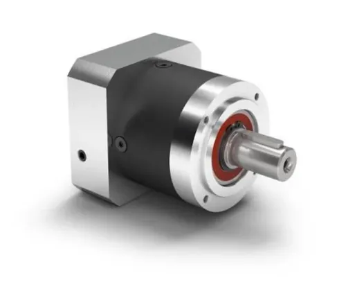
A gearbox, screw, or pulley changes both the torque and speed the motor sees. Define the gear ratio N as motor speed divided by load speed: load torque is divided by N, while load inertia becomes reflected inertia of Jload/N² at the motor. Include gearbox efficiency, because losses reduce the torque available at the output.
For a screw, motor speed equals linear speed divided by screw lead; a smaller lead reduces torque demand but raises motor rpm. For a belt drive, motor torque equals linear force multiplied by pulley radius, while speed equals linear speed divided by that radius.
A smaller pulley lowers torque demand but can push the motor beyond its rated speed. Add acceleration torque, J·α, using the combined motor-side inertia.
Check the full speed–torque curve at the actual DC-bus voltage, cable length, drive current limit, and operating temperature. The motor must deliver the required continuous torque at operating speed and peak torque during acceleration; a catalog no-load speed proves nothing.
High reflected inertia can lengthen settling time and make tuning sensitive, so do not assume a universal 1:1 inertia match.
- Convert every load to the motor shaft before selecting the motor:
- Calculate reflected load torque after ratio and efficiency losses.
- Calculate reflected inertia for the load, gearbox, pulley, screw, and moving mass.
- Confirm acceleration torque plus process torque stays inside the peak-torque region.
- Check deceleration and lowering for regenerated energy and DC-bus overvoltage.
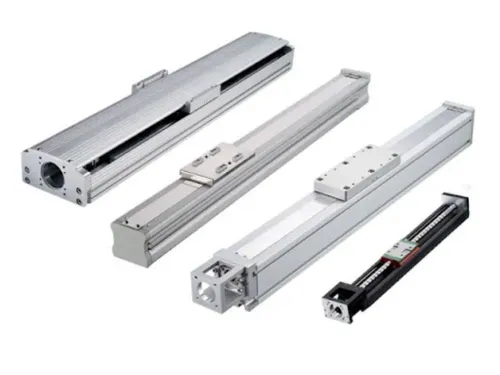
- Give OLE Automation Inc the carriage mass, guide preload, screw lead, pulley diameter, travel speed, and acceleration when checking a linear-axis component choice.
Specify the Positioning Performance You Actually Need
Turn the machine’s target into a load-side specification, not an encoder-count promise. State the commanded resolution, unidirectional and bidirectional repeatability, absolute accuracy, maximum contouring error, and settling time at the actual tool or workpiece.
- Define commanded resolution as the smallest position increment the controller must issue. Do not confuse it with achieved accuracy.
- Specify repeatability by test direction. A mechanism can return consistently from one direction yet show large bidirectional error from backlash, reversal friction, or coupling windup.
- Set absolute accuracy against a physical reference across the full travel. Include ballscrew or gearbox pitch error, encoder interpolation error, thermal growth, servo following error, structural vibration, and homing-reference repeatability.
- Set settling time from the end of the move to the instant position remains inside the allowed error band. A motor that reaches the target but rings outside that band has failed the requirement.
- Choose feedback at the point that matters. A motor-mounted encoder cannot measure output-side backlash or torsional compliance; tight load-side accuracy after reversals may require an output-side or dual-loop encoder.
Check the transmission before increasing nominal encoder counts. Gearboxes, belts, couplings, and screws can dominate final error, while a high reflected-inertia ratio can lengthen settling time and make tuning sensitive. Select the encoder and drive together: verify feedback resolution, interpolation limits, update rate, bandwidth, and whether the drive supports the required dual-loop control.
Match the Motor to the Drive and Regeneration Limits
A motor can satisfy the RMS torque requirement and still fail during acceleration because its peak torque, peak current, or drive overload duration is too low. Compare the complete speed–torque envelope at the actual DC-bus voltage and operating temperature, not the catalogue’s nominal test condition.
| Check | Confirm | Failure prevented |
|---|---|---|
| Electrical | Motor voltage, continuous current, peak current, overload time, cable length, and drive current limits match; check torque at required speed, including the constant-power region above base speed. | High-speed torque loss, overcurrent trips, and voltage-limit faults |
| Feedback | Encoder type, resolution, wiring, and feedback protocol are supported by the drive. | Commutation errors, position faults, and uncontrolled stopping |
| Communication | Drive network, update rate, node address, and command mode match the controller. | Lost commands, delayed corrections, and nuisance communication alarms |
| Cooling | Continuous torque rating matches the actual mounting orientation, ambient temperature, altitude, enclosure, nearby heat sources, and cooling method. | Winding overheating despite a catalogue-compatible rating |
| Braking and regeneration | Calculate returned kinetic and potential energy; verify the internal resistor, external braking-resistor requirement, DC-bus overvoltage threshold, and allowable regeneration duty. | Deceleration overvoltage trips and resistor overheating |
For a vertical axis, calculate upward and downward motion separately. Gravity acts continuously, and the motor must produce motion torque while the brake normally holds position rather than replacing that torque. Confirm the brake’s voltage, release time, holding torque, and stopping duty before relying on it.
Validate the Choice Against the Full Duty Cycle
Approve the motor only after calculating the complete time history at the actual DC-bus voltage and operating temperature. Do not apply an informal safety factor to rated torque: include acceleration, deceleration, dwell, reversals, load changes, maximum speed and the worst-case thermal condition.
1. Calculate RMS torque over the entire duty cycle and compare it with the motor’s continuous torque rating. Then compare every acceleration, deceleration and disturbance event with peak torque, peak current and the permitted overload duration.
2. Plot the required torque against speed on the manufacturer’s complete speed–torque curve. Confirm operation inside the constant-torque region below base speed and the constant-power region above it, where torque falls because of back-EMF and DC-bus voltage limits.
3. Calculate regenerative energy for each stop, reversal, lowering movement and vertical-axis descent. Check the drive’s internal resistor capacity, required external braking resistor, DC-bus overvoltage threshold and allowable regeneration duty; adequate motor torque does not prevent a deceleration fault.
4. Recalculate upward and downward vertical-axis cases, including continuous gravity torque. Treat the holding brake as a parking device, not as motor torque during motion.
5. File the calculation with the selected motor-drive speed–torque curve, current limits, cable length, overload chart, thermal assumptions, braking-resistor sizing, duty profile and drive parameter set. Record the acceptance test results for peak speed, positioning, temperature and fault-free stopping.
Frequently asked questions
How do you calculate the torque a servo motor must deliver?
Add load, acceleration, friction, gravity, and cutting-force torque, then apply a documented design margin based on the complete motion profile.
How does a transmission affect servo motor torque and speed?
Reflect the load through the gear ratio and efficiency: gearing changes the motor-side torque, speed, and reflected inertia.
Which positioning specifications matter when choosing a servo motor?
Define accuracy, repeatability, encoder resolution, backlash, settling time, and the required position under the actual load.
Why must you check the servo drive and regeneration limits?
The motor and drive must support peak current, continuous current, braking energy, bus voltage, and regenerative capacity during the motion cycle.