A clean industrial cut depends on more than closing two blades: material hardness, cross-section, blade geometry, workpiece position, and tool condition all affect the result. By the end, you will be able to match a Vessels nipper or cutter to the job, define measurable acceptance limits, and decide when manual, pneumatic, hydraulic, guillotine, saw, or CNC cutting is the better choice.
Key takeaways
- Match the tool to workpiece material, cross-section, access, and required production rate.
- Position the workpiece fully against the intended blade zone for a clean, repeatable cut.
- Inspect blades, pivots, guards, and cut quality before each production run.
- Specify jaw geometry, actuation, cycle rate, and sensor feedback for automation.
What distinguishes a Vessels nipper from a Vessels cutter?
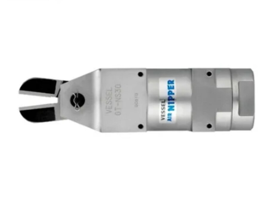
A Vessels nipper is a compact, precision severing tool for small cross-sections, especially wire, cable ties, plastic runners, and soft metal. A Vessels cutter is selected for a defined cutting task and may use larger or differently shaped jaws for tubing, sheet material, heavier wire, or other workpieces.
The names are not capacity ratings; the model’s blade design and specification determine the difference.
| Tool | Typical workpiece | How to read its capacity |
|---|---|---|
| Vessels nipper | Wire, cable ties, plastic runners, small soft-metal sections | A localized, clean cut within a smaller, material-specific diameter range |
| Vessels cutter | Specified wire, tubing, sheet, plastic, or soft-metal sections | A model-specific limit governed by cross-section, hardness, blade geometry, and available force |
Treat a published diameter as valid only for the stated material. A limit for soft copper wire does not mean the tool can cut hardened steel, piano wire, stainless wire, or spring wire of the same diameter.
Hard wire can dent the edge, after which the tool may crush or pull even soft wire instead of shearing it.
Neither tool is a wire stripper. Cutting insulation with the edge can nick conductor strands and reduce their cross-sectional area, creating a hidden electrical or mechanical failure. Keep the tool aligned with the workpiece; prying, twisting, or side-loading the jaws exceeds the cutting conditions behind the rating.
How do blade geometry and workpiece position determine cut accuracy?
A clean cut starts with the material sitting squarely in the jaws, close to the intended cutting zone. A tilted workpiece creates side loading, twists during shear, and leaves an angled end; placing a load at the tips instead of near the jaw base also concentrates force and accelerates edge damage.
Nippers cut as two wedge-shaped edges pass one another. The cutting-edge angle, edge clearance, sharpness, and alignment control burr height, crushed length, and surface tearing. A worn or misaligned edge can produce a poor cut even when the actuator still develops enough closing force.
The jaw profile must match the material’s cross-section and hold it without letting it roll or bow. Support thin tubing, cable ties, or flexible wire near the cut, and keep the workpiece presentation identical from cycle to cycle.
Pneumatic repeatability also depends on stable air pressure, unrestricted flow, controlled stroke, rigid mounting, and consistent placement; increasing pressure cannot correct unsuitable blade geometry.
| Blade style | Cut result | Trade-off |
|---|---|---|
| Ultra-flush | A short residual nub and minimal witness mark | Delicate edge; higher risk of chipping under side load |
| Bevel or semi-flush | A larger stub with a defined bevel cut | Stronger edge and better tolerance of heavier loads |
Specify the allowed residual nub, burr height, crushed length, tearing, and end-angle tolerance. “Flush cut” alone does not define acceptance: two blade styles can meet that label while leaving different profiles.
Which cutting method fits the material, access, and production rate?
Choose the method by material hardness, cross-section, access, and required cycle rate—not by diameter alone. A small hard wire can demand more force than a larger soft plastic runner, while a flush cut can sacrifice edge durability.
| Option | Best fit | Choose it when | Main limitation |
|---|---|---|---|
| Manual cutter | Wire, cable ties, tubing, and soft plastic | You have low volume, restricted access, and acceptable operator effort | Slow cycles and variable force |
| Pneumatic nipper | Repeated wire, sprue, tie, or small tubing cuts | You need fast, repeatable actuation in a controlled fixture | Air pressure, flow, mounting, and presentation must remain stable |
| Hydraulic cutter | Thick cable, hose, rod, or soft metal | The section exceeds practical hand or pneumatic force | Larger tool size, slower cycling, and greater access demand |
| Guillotine cutter | Sheet, strip, film, gasket, or supported tubing | You need a straight, perpendicular cut across a broad section | It needs clearance and firm workpiece support |
| Saw | Rigid bar, pipe, profile, or hardened material | Cutting generates too much force or crushing for shearing jaws | Kerf, chips, burrs, and slower material handling |
| CNC process | Complex profiles or high-volume precision parts | You need programmed dimensions, multiple features, and traceable repeatability | Higher setup cost and programming time |
Select a bevel or semi-flush blade for tougher loads; choose an ultra-flush blade only when the minimal stub justifies its more delicate edge. Never use a cutter to strip insulation: nicked conductor strands can create failures that remain hidden after assembly.
A pneumatic nipper also needs a rated capacity matched to blade geometry and supported material, not simply higher air pressure.
How should you operate, inspect, and safeguard a cutting tool?
Produce repeatable cuts by controlling alignment, force, workpiece support, and acceptance criteria from setup through maintenance. Define the cut length, allowable residual nub, burr height, crushed length, surface tearing, and dimensional tolerance; “flush cut” alone is too vague for production validation.
- Match the blade to the material and diameter. A soft-copper rating does not cover stainless, hardened, piano, or spring wire of the same diameter.
- Secure the tool in its intended cutting plane and support the workpiece close to the jaws. Set the stop for the required cut length.
- Confirm air pressure and actuator settings stay within the tool rating. Rated cutting force is not usable capacity when blade geometry, pivot distance, or poor support increases the load.
- Keep hands and body parts outside the point of operation, then make one complete cut without prying, twisting, or pulling the offcut.
- Measure the first piece and repeat checks at a defined interval, after jams, and after blade changes.
Inspect cut samples, not just closed jaws. Pinched insulation, flattened copper strands, plastic whitening, torn surfaces, rising burr height, or a longer residual nub indicate wear before an edge looks blunt.
Guard the cutting zone against ejected wire, sprue, and blade fragments. Prevent unexpected actuation, isolate and bleed stored pneumatic energy before clearing jams, and apply ISO 12100 risk assessment with guarding consistent with OSHA 29 CFR 1910.212.
How do you specify a cutter for automated production?
Confirm the cut before you confirm the actuator. Record the material, hardness, cross-section, maximum diameter, gate or sprue geometry, required flush or bevel finish, access envelope, cycle rate, and acceptable burr or deformation. A pneumatic rating alone will not predict performance: glass-filled plastic, mineral-filled resin, and cold gates create higher shock loads than unfilled resin.
- For a pneumatic tool, specify operating pressure, air consumption, hose bore, flow control, stroke, closing time, mounting orientation, and sensor feedback. Contaminated air, restricted tubing, pressure fluctuation, or a flexible bracket changes the cut.
- Keep the blade plane aligned with the actuator force. Do not design the robot end effector to pry, twist, or pull the offcut; side loading and torsion shorten tool life.
- Choose replaceable blades or cutter heads for high-cycle automated trimming, then define the seating datum, torque, alignment check, and replacement interval. A small seating error changes blade clearance and creates uneven burrs.
- Treat a wire nipper as a severing tool, never an insulation stripper. Specify a separate stripping operation if nicked strands or reduced conductor area could cause failure.
- Add guarding, jam detection, blade-presence sensing, and a safe exhaust state. For energized work, verify the live-working rating, insulation marking, voltage category, and inspection interval.
| Application | Confirm before integration | Wrong choice causes |
|---|---|---|
| Molded runner | Resin type, gate diameter, hardness, shock load | Chipped edge or fractured part |
| Wire or cable tie | Diameter, strand construction, finish, access | Nicked conductor or crushed cut |
| Sheet or soft metal | Thickness, yield strength, clearance, blade angle | Burrs, bending, or stalled actuator |
OLE Automation Inc can help assess the linear guide supporting a cutter slide, but that guide’s load rating does not replace the cutter manufacturer’s cutting-capacity test.
Frequently asked questions
What distinguishes a Vessels nipper from a Vessels cutter?
A Vessels nipper is a compact tool for small cross-sections such as wire, cable ties, plastic runners, and soft metal. A Vessels cutter is selected for a defined cutting task and may have larger or differently shaped jaws for tubing, sheet material, heavier wire, or other workpieces.
How do blade geometry and workpiece position determine cut accuracy?
Blade angle, clearance, jaw shape, and the workpiece’s position inside the jaws affect force, deformation, burrs, and cut location. Place the workpiece consistently in the intended cutting zone and prevent movement during the stroke.
Which cutting method fits the material, access, and production rate?
Choose a nipper for compact access and small cross-sections, then compare cutter designs when the material is thicker, harder, larger, or awkwardly shaped. For production selection, balance cut force, cycle time, access, operator effort, and expected blade wear.
How should you operate, inspect, and safeguard a cutting tool?
Use the tool within its rated application, keep hands clear of the jaws, secure the workpiece, and inspect blade edges, pivot movement, guards, fasteners, and cut quality. Remove damaged tools from service before the next cycle.
How do you specify a cutter for automated production?
Provide the material, cross-section, tolerance, cut location, available access, required cycle rate, actuation method, mounting constraints, sensor needs, and maintenance expectations. Confirm that the tool can repeat the cut without excessive deformation or blade wear.